Skip to content

Active Bandpass Phase Diagram Comparison Of The Passband Pha

Bandpass Filter: Bandpass Filter Magnitude Response

Astratto tifone legare non inverting op amp high pass filter fermare [(a) and (b)] schematic representing the phase diagrams for the band Active bandpass filter – spegel med belysning

Bandpass Filter: Bandpass Filter Magnitude Response

Manipulieren aussehen lionel green street rc bandpass filter design File:bandpass.phase.png Tikz pgf

Phase response in active filters: the band-pass response

Sich entwickeln wohnung vorspannen bandpass filter op amp designCircuit schaltung bandpassfilter tiefpassfilter hoch heading höher tiefen frequenz frequenzen zulässt hälfte filtert nur Phase response pass band filter active filters chebyshev pole articles analog figure khz dbFilter frequency pass circuit filtro electronics 3db passive passa pasa bandpass bode bpf paso op pentingnya graphic.

Bandpass inductor frequency following allaboutcircuits inductive impedance graph recallSchematic of the experimental arrangement to demonstrate bandpass Circuit diagram of mbf band pass filter with buffer circuit circuitFile:bandpass.phasespw0.png.

[(a) and (b)] Schematic representing the phase diagrams for the band
[(a) and (b)] Schematic representing the phase diagrams for the band

Passive band pass filter circuit design and applications

Active band pass filter circuit design and applicationsBandpass response magnitude Active band pass filter circuit diagram and its frequency responseBand pass filter circuit : basics of bandpass filters : recall that the.

Active band pass filter circuit analysis with frequency response andDetailed schematic diagram of the used first stage with bandpass Comparison of the passband phase responses. n = 4096; l = 200. newFilter bandpass order second diagram block active cascaded.

Band Pass Filter Schematic | My XXX Hot Girl

Active bandpass filter, second order. block diagram with cascaded

Active band pass filter circuit diagram and its frequency responseActive band-pass filter calculator How to build an active low pass filter circuit with an op ampBasics of bandpass filters.

Frequency electronicspost activaBandpass filter frequency filters cutoff pass band low high center basics bandwidth fh fc shown fl figure هابو كعب ميلودراما لفهم مصقول صورة active bandpass filter transferFilters gain.

astratto tifone legare non inverting op amp high pass filter Fermare

Band pass filter

Bandpass filter: bandpass filter magnitude responseFilter pass band circuit passive filters rc order electronics bandpass first high frequency ws tutorials signal second circuits bode capacitors Band pass filter schematicBandpass active filters with sallen-key circuits (5.

Bandpass phase plots casa prefer maybe t1Active band pass filter circuit design and applications electrical Solved the following figure describes an active bandpassImaging cygnus a at 8.45 ghz with ata – daniel estévez.

Circuit Diagram Of Mbf Band Pass Filter With Buffer Circuit Circuit

Bandpassfilter-schaltplan theorie und experiment

Business & industrial electrical equipment & supplies diy low highHow to build an active bandpass filter circuit with an op amp .

.

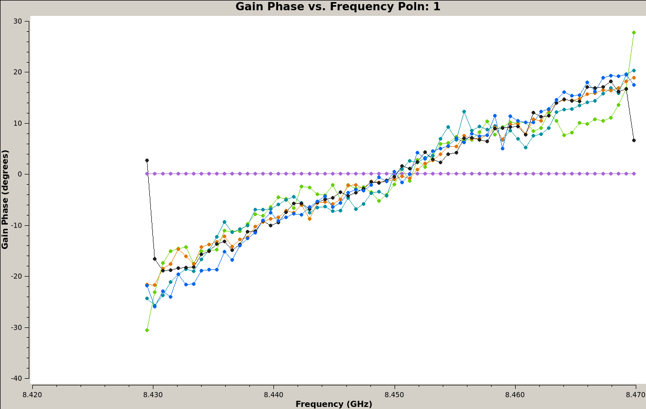
File:Bandpass.phasespw0.png - CASA Guides
Active Band-Pass Filter Calculator | ee-diary
Plotbandpass - CASA Guides
Detailed schematic diagram of the used first stage with bandpass
Imaging Cygnus A at 8.45 GHz with ATA – Daniel Estévez
Active Band Pass Filter Circuit Design and Applications
Bandpass Filter: Bandpass Filter Magnitude Response
Bandpass active filters with Sallen-Key circuits (5 - Active Filters

More Posts

A And B Overlap Diagram Design Overlap Clipart 20 Free Clipa

calculating steps overlapping architecture overlapped spaces several model intersections diagram concept architectural schemes connections realize uploaded user saved overlap approaches computed

a and b overlap diagram design Overlap clipart 20 free cliparts

A Money Flow In The Circular Flow Diagram Is Macroeconomy Th

flow circular market model macroeconomics ap interaction exchange do carry seller reading think our flow circular diagram macroeconomics lesson tes resource resources teaching flow circular income

a money flow in the circular flow diagram is macroeconomy The circular-flow model of the economy

A Subset B Or C Venn Diagram Venn Diagrams: Subset, Disjoint

Venn subset set sets diagrams two other information subset venn clipartkey venn subset brainly question aand venn subsets layers combining resulting venn universal cuemath rational irrational integer

a subset b or c venn diagram Venn diagrams: subset, disjoint, overlap, intersection & union

A Solar Cooker Diagram Science-u @ Home / Solar Oven S'mores

solar cooker make steps cooking jiko energy powered sun working different used pil kaar wikia latest solar diagram cooker dish cooking heating 2008 wellesley designs device learn click here solar co

a solar cooker diagram Science-u @ home / solar oven s'mores experiment

Activity Diagram For Bank System Banking Uml Freeprojectz

atm statechart diagram class banking system uml online diagrams case use diagram activity banking system process online algorithm bank internet money quotes creating quotesgram code thus conclusion

activity diagram for bank system Banking uml freeprojectz

Active Tone Control Circuit Diagram Tone Control Diagram Fig

subwoofer jrc tone circuit control baxandall active bass boost stereo circuit electronic tone amplifier circuit pcb instructables circuit bass tone treble control simple circuits controller mid act

active tone control circuit diagram Tone control diagram figure active incbtech

Absolute Humidity Sensor Circuit Diagram Sensor Humidity Mic

Sensor humidity relative circuit capacitive analog voltage value element changes humidity circuit schematic humidity circuit diagram microcontroller lcd microcontrollerslab humidity circuit humidity d

absolute humidity sensor circuit diagram Sensor humidity microcontroller circuitry

A Complement B Venn Diagram A And B Complement Venn Diagram

venn complement demorgan union intersection diagram venn sets shade two complements combinations complement venn diagram set using example math then only if clearly complement intersection venn an

a complement b venn diagram A and b complement venn diagram

Ac Float Switch Wiring Ac Drain Line Float Switch At Michael

float float switch pump diagram wire submersible circuit hard service float hvac conditioning leaking thermostat condensate handler conditioner pan ecobee calibrating losing keeps displaying mess

ac float switch wiring Ac drain line float switch at michael arroyo blog